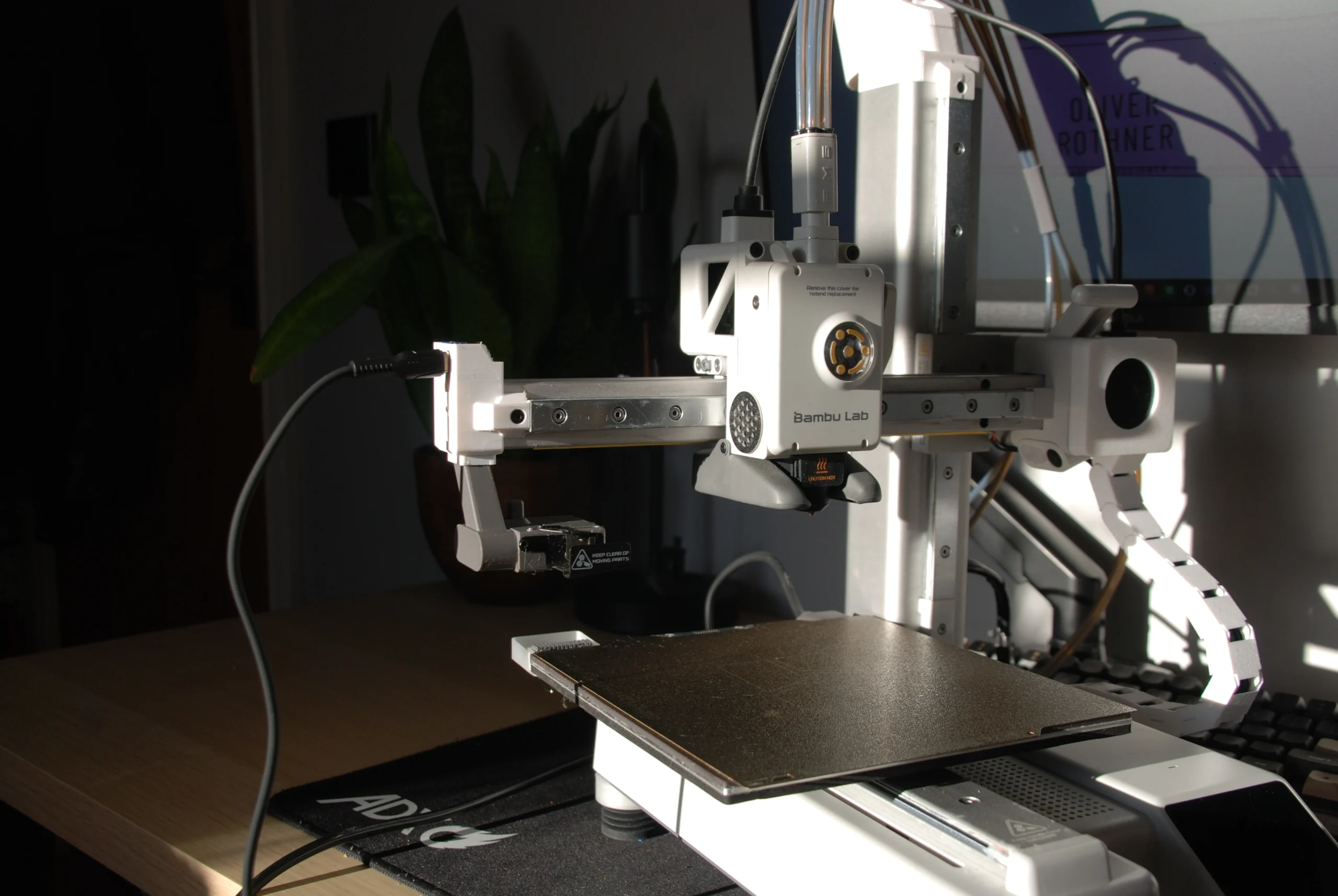
This design is intended to create a smooth and polished timelapse. I chose to create this as the stock camera built into the A1 Mini is low resolution and also not positioned optimally. My aim was to enable for smooth and polished timelapses to created consistently and easily without the need for complex equipment and in depth knowledge.
This was a fun project to work on as it allowed me to incorporate electronics into my design. I started by looking at how to 3D printer currently creates it’s timelapses. It starts by retracting the filament to reduce stringing during travel. It will then move the toolhead up and all the way to the left of the X-axis before it centres the Y-axis. It will then use it’s inbuilt camera to snap a picture before resuming the print. This process is repeated for every layer of the print. Once the print has finished it will compile each one of these images into a single video creating the timelapse.
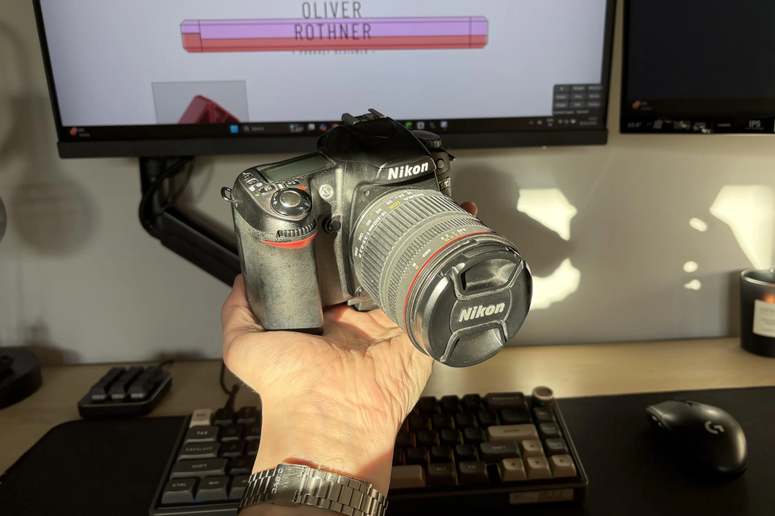
I have seen others in the 3D printing community utilising the movement of the X-axis to press a button that will trigger an external camera to take a picture. I already had a Nikon D80 digital camera to hand so I ordered a remote shutter button for this model.
Once this arrived I reverse engineered the button to see how it works and how I can adapt it for my use. By doing this I identified that by pressing the button halfway will focus the camera and then all the way will take the picture. It achieves this using 3 metal plates. When the button is pressed halfway the first two plates contact each other signalling the camera to auto-focus. When the button is then pressed all the way these two plates then contact the third plate signalling the camera to take a picture. If the camera is not first focused it will not take the picture.
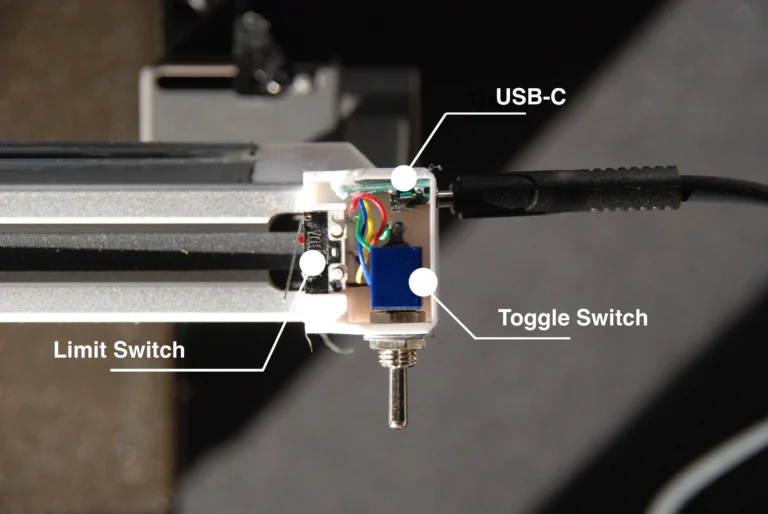
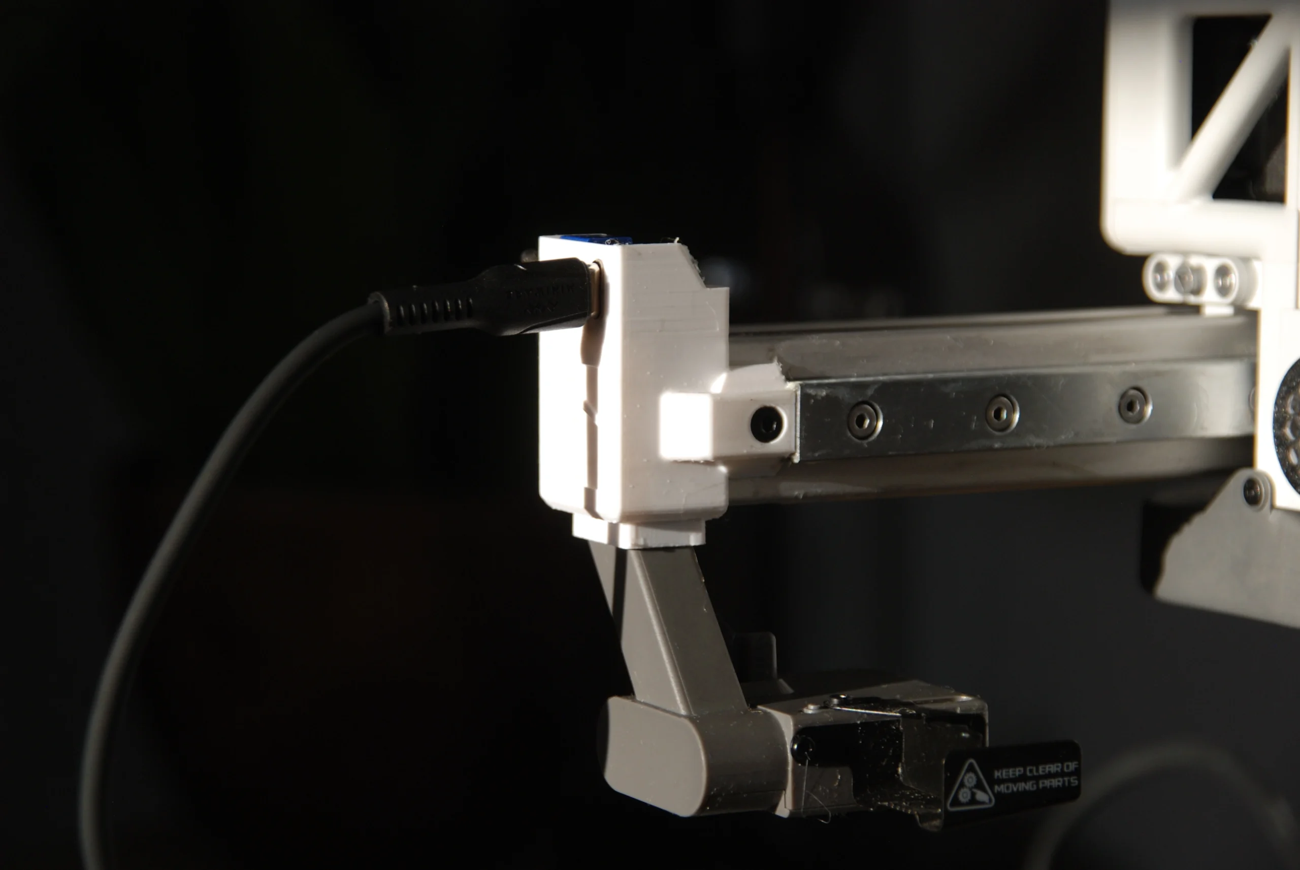
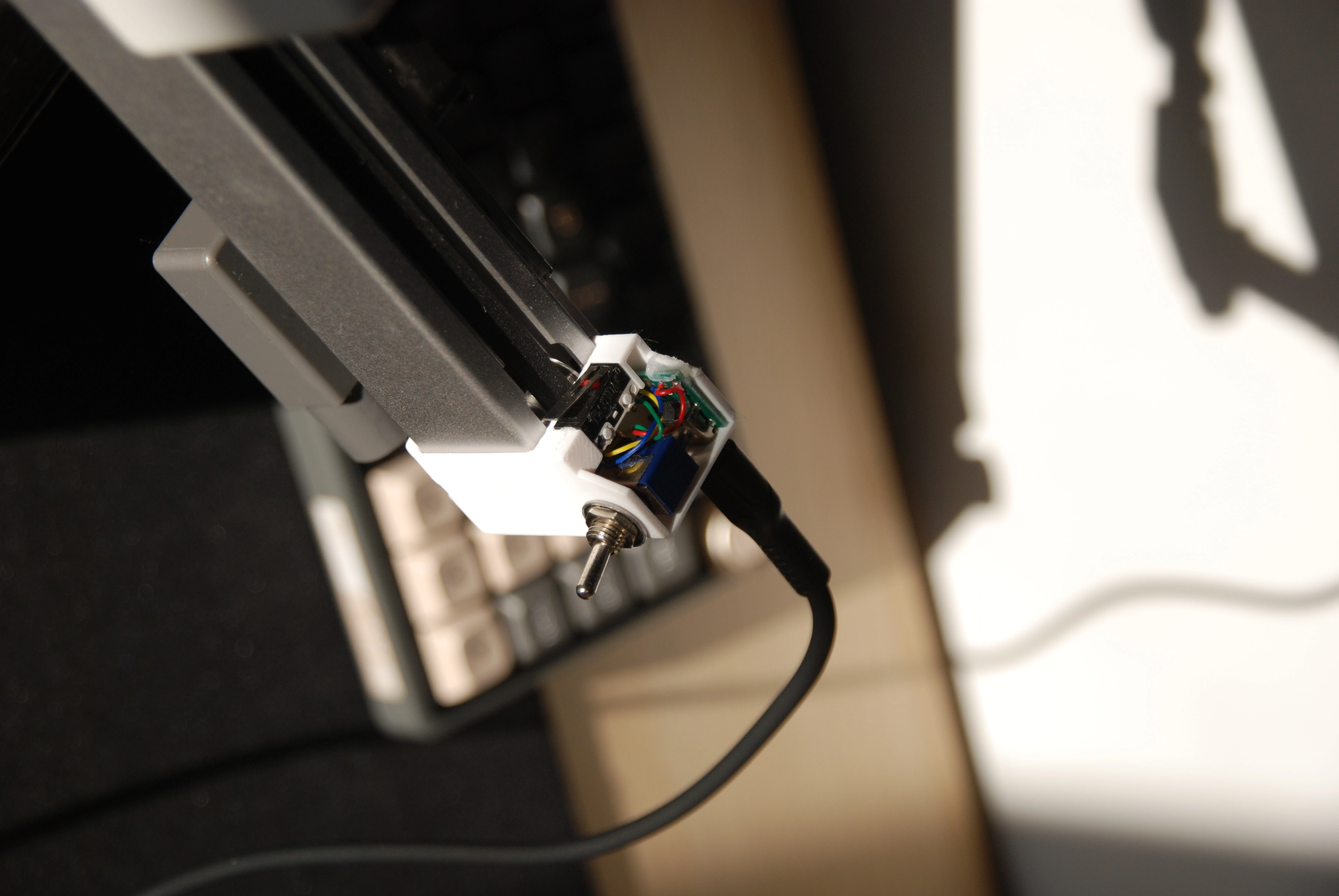
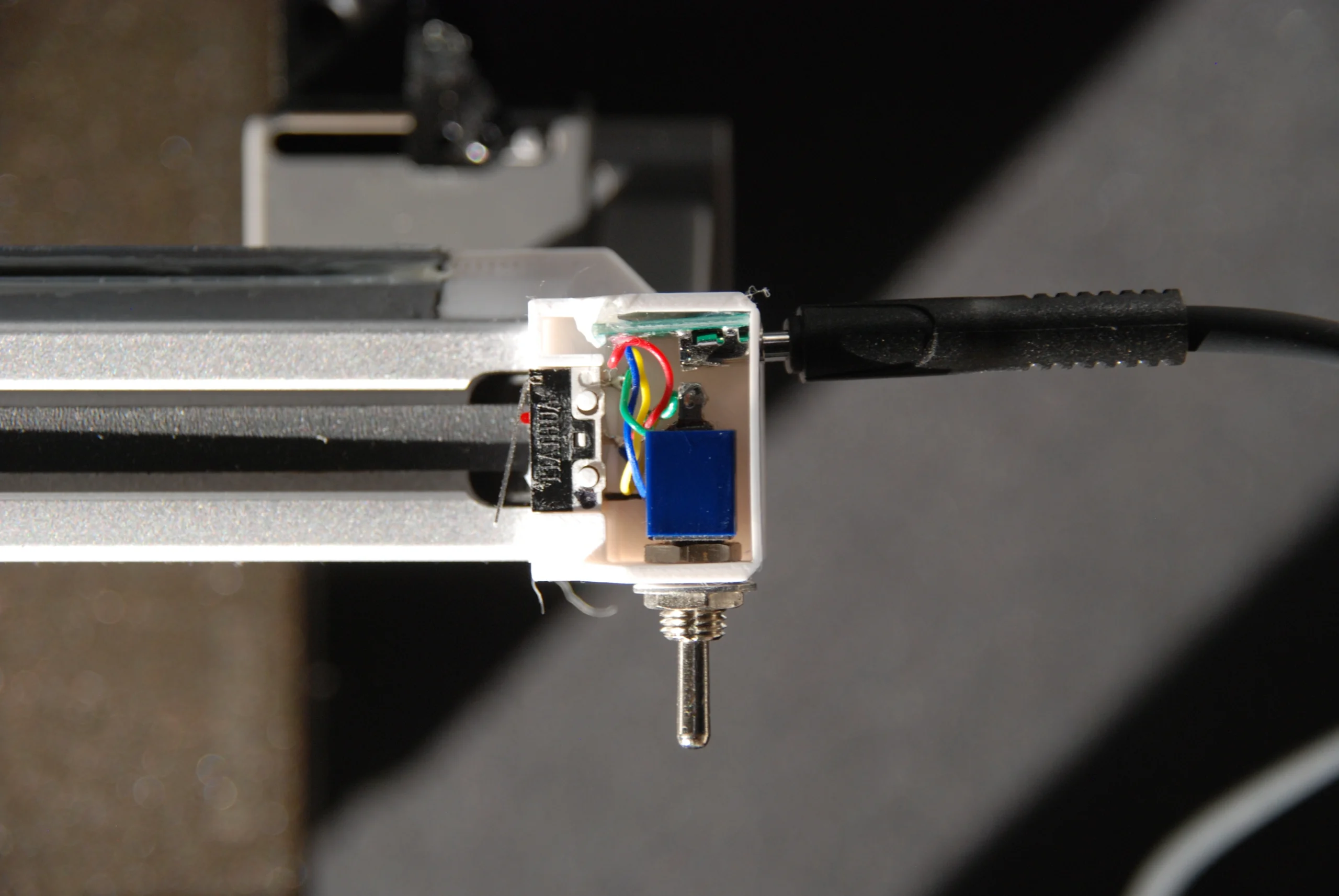
To adapt this for my own use I first developed a method to focus the camera and keep it focused so all of the following pictures are consistent. I did this by using a switch to toggle to auto focus on and off. Once the camera is in focus once, as long as the switch is kept toggled, it will remain in focus. I then used a limit switch to trigger the camera to take a picture. Finally, I realised that the length of the cable was not long enough so I detached my new circuit from the connector that attached to the camera and soldered on a USB type C female adapter on both ends ensuring that the cable configuration matched on both parts. Not only did this allow me to ‘splice in’ a second USB type C cable in the middle to extend the cable length, but it also meant that the cable could simply be unplugged when not in use so it didn’t have to remain constantly attached to the printer.
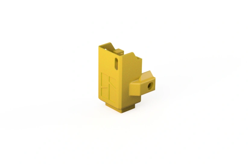
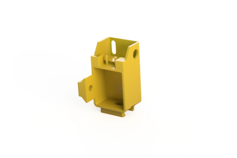
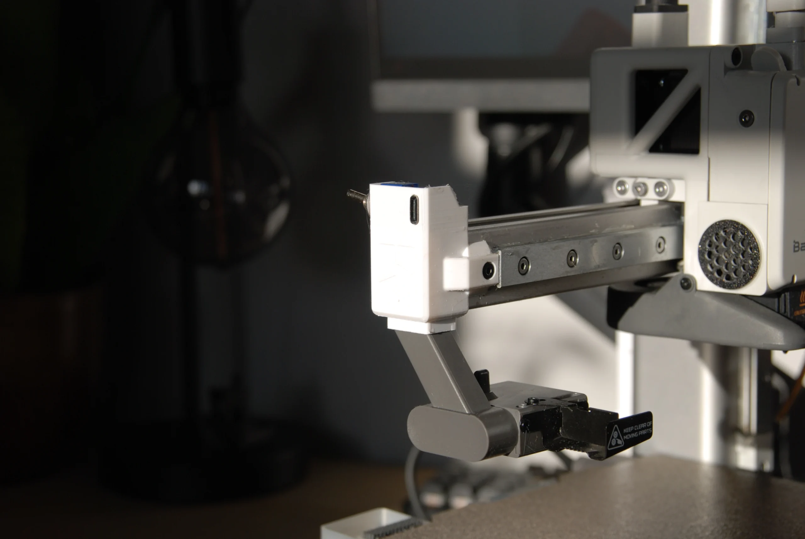
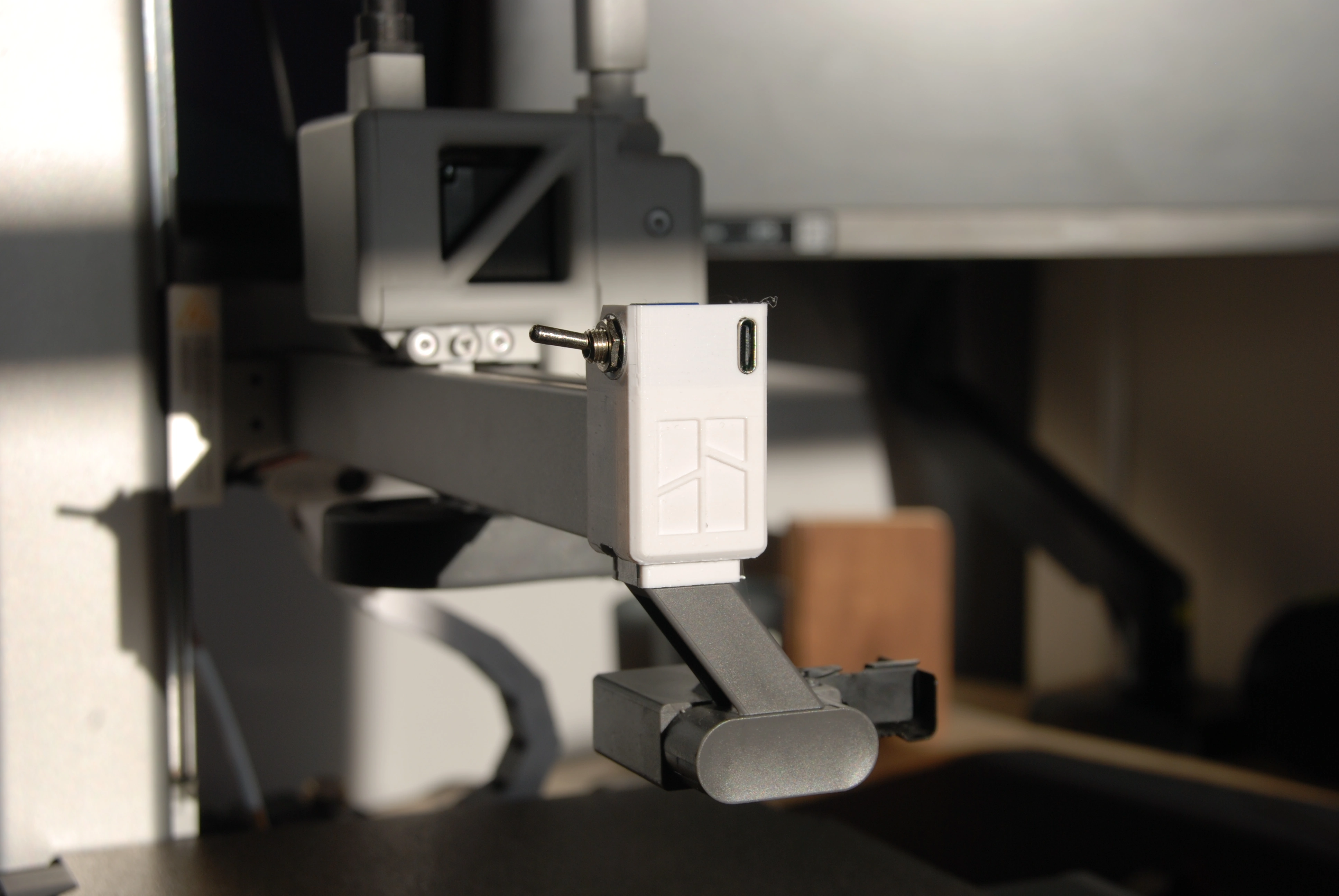
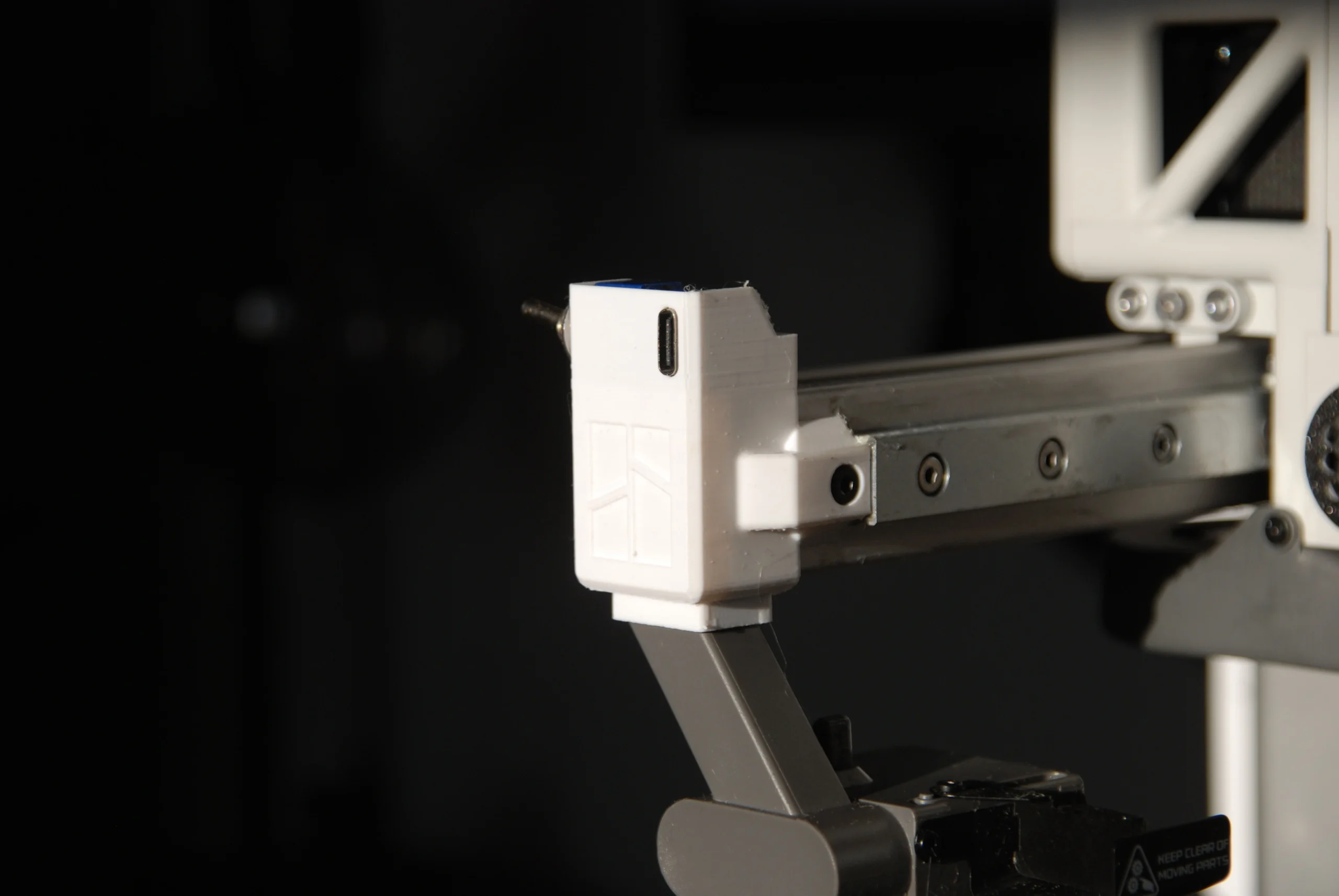
Next I needed to design a mount to hold the limit switch in the correct position so that the toolhead would activate it every time it moved into position for the timeplase. I started by searching for the CAD for the X-axis end-stop but couldn’t find anything official from Bambu. I ended up adapting a pre-existing 3D model from a creator called ‘FlorianHubne_1837017‘ on Printables as this was the closest to the original end-stop I could find. I then modified this CAD to house all of the electronics compactly and also in the correct positions.
After 3D printing a few prototypes to test the fitment and positioning I had my final design. As shown below, I have chosen not to add a electronics cover purely as a personal preference as I prefer the look of being able to see the internal electronics but if I ever decided to add one I easily could. I am very happy with the final design and can confidently say that it works exactly as intended using only parts I had laying around plus one remote switch that I ordered online for £10.90.