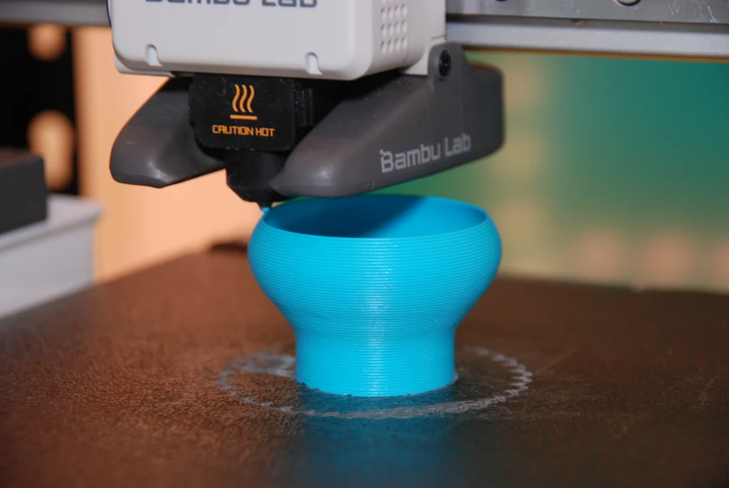
What are layer lines?
Layer lines are the horizontal lines across a part formed during 3D printing. Every method of 3D printing creates these lines to varying degrees, but FDM typically has the most pronounced. This is because it tends to operate at lower layer resolutions (0.06mm – 0.4mm+). They are created by the movement of the nozzle in the Z-axis as the printer ‘stacks’ layers on top of each other. This is also what causes the stepping effect seen on curves along the Z-axis. These layers can often be felt by running your nail across the surface of a 3D printed part.
How to effectively hide them
Reduced layer height
So how can you reduce them? The most common method is to use a smaller layer height. This increases the resolution of the print by minimising the thickness of each layer, making the lines less obvious. A smaller layer height is often paired with a smaller diameter nozzle, which also increases resolution in the X and Y axes. Whilst this method has a clear and direct effect on quality, it significantly increases build time. This is because the printer must produce more layers to achieve the same height, as well as more passes in the X and Y axes. This increase in print time is often what discourages people from reducing layer height.
Fuzzy Skin
For this reason, many people look to other methods to disguise their layer lines. A commonly used option is activating a slicer setting called ‘fuzzy skin’. The slicer software converts a 3D model into many thin layers and generates the G-code the printer follows. Fuzzy skin works by introducing small, random offsets to the nozzle’s path along the outer walls in the X and Y plane. This creates a textured surface that diffuses light and reduces the visibility of layer lines. The roughness can be controlled by adjusting the ‘fuzzy skin point distance’ and ‘fuzzy skin thickness’, which determine the spacing and magnitude of these surface variations.
Sanding and Painting
Another common approach, particularly when tight tolerances are not required, is sanding. This usually involves increasing the wall count and the number of top and bottom layers to thicken the outer shell. Doing so allows material to be sanded away without risking exposure of the internal infill. Filler primer and paint are often used alongside sanding, or on their own if the surface is already relatively smooth.
Vapour Smoothing
Vapour smoothing is a method that cannot be used with all materials but produces a smooth, glossy finish when compatible. The most common material used for this process is ABS. Although dedicated vapour smoothing systems are available, the basic process requires acetone, an airtight container, a paper towel, and a compatible printed part. The towel is soaked in acetone and sealed inside the container with the part, ensuring they do not touch. The acetone vaporises and settles onto the surface of the print. This causes surface dissolution: the solvent softens and partially dissolves the outer polymer layer, allowing it to reflow and smooth out the layer lines before solidifying again.
Build Orientation
Finally, a simple but often overlooked method is correctly orientating the part on the build plate. Adjusting orientation can reduce the visual impact of layer lines or position them in less noticeable areas of the geometry. This is a skill that improves with experience, as you become better at identifying the optimal orientation for both strength and surface finish.

WRITTEN BY OLIVER ROTHNER
Award-winning product designer and engineer.
Currently working as Project Manager at Pro2Pro whilst obtaining further qualifications.